51
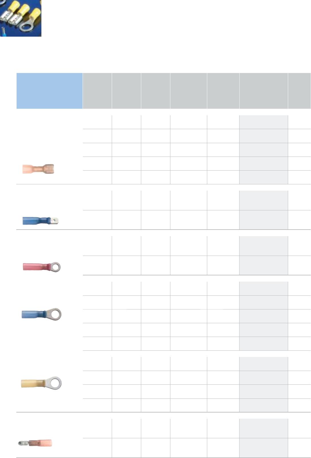
Colour Ø Length
Quantity in the
assortment
Part number PU
in pcs.
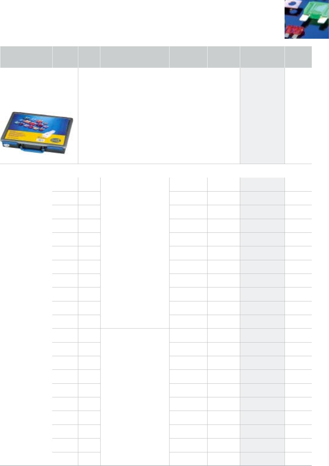
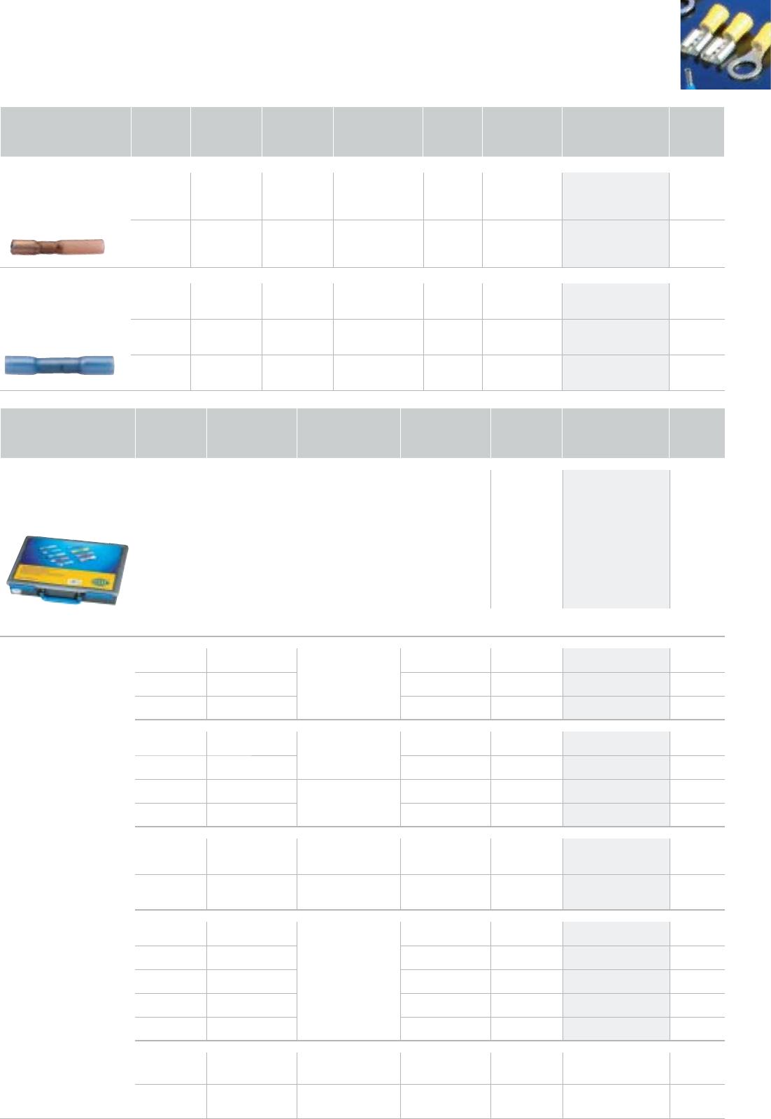
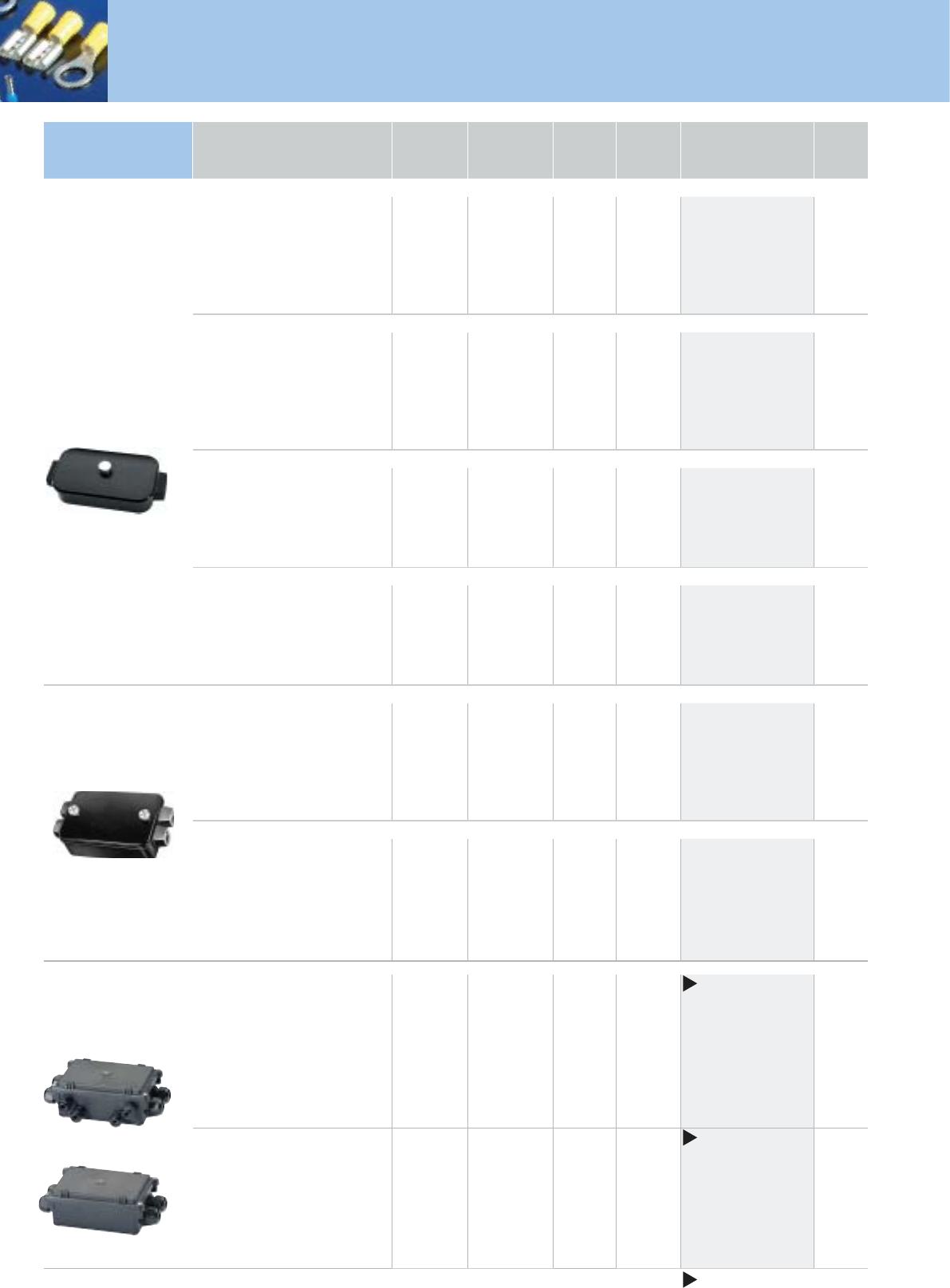
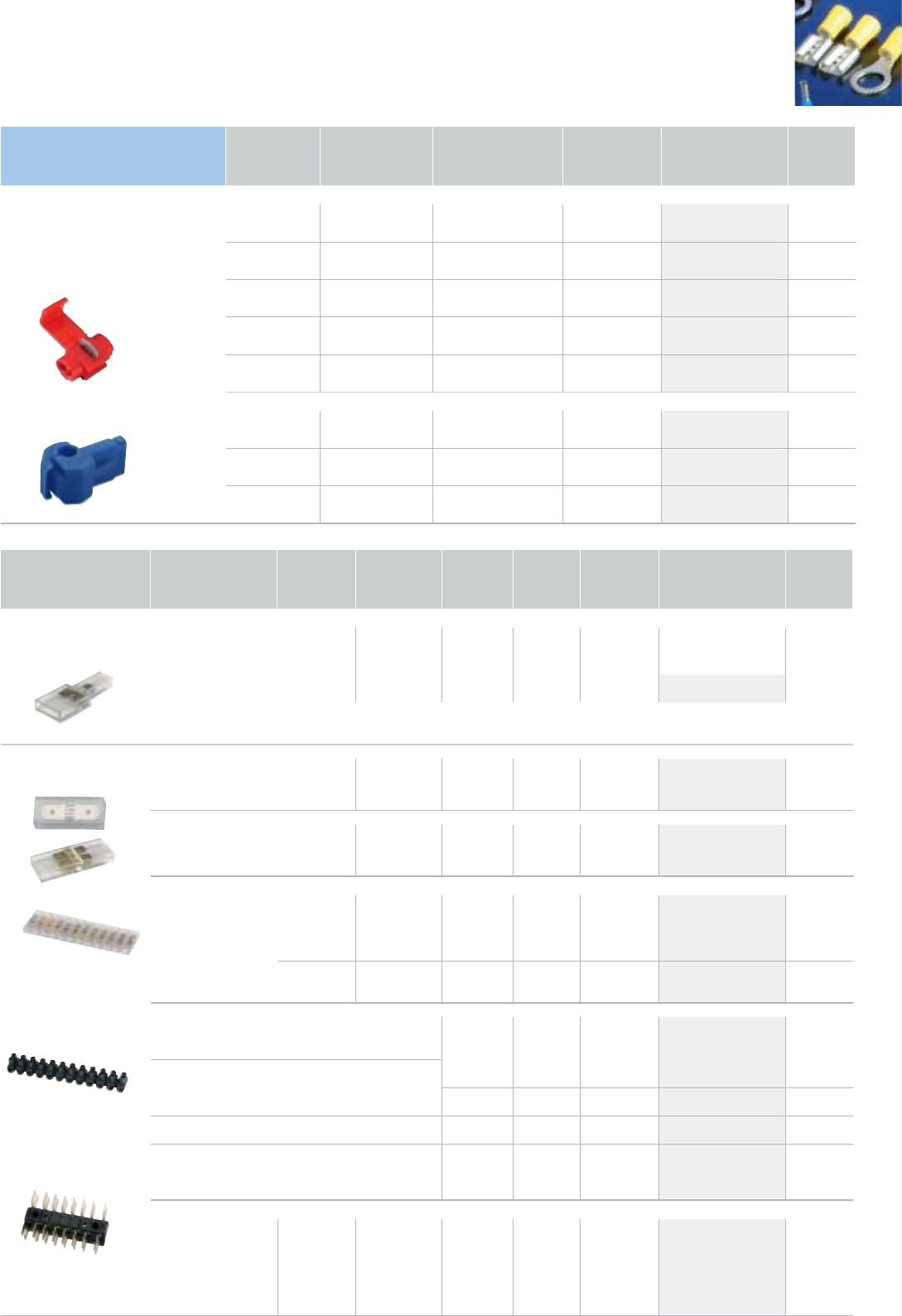
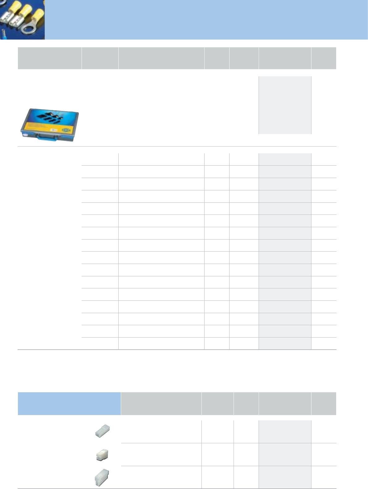
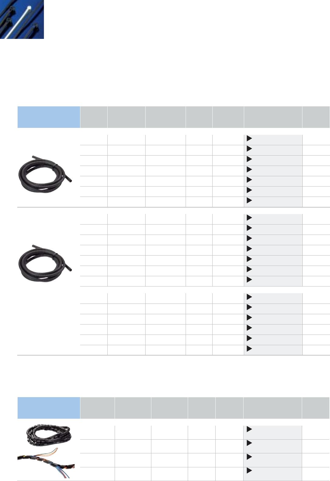
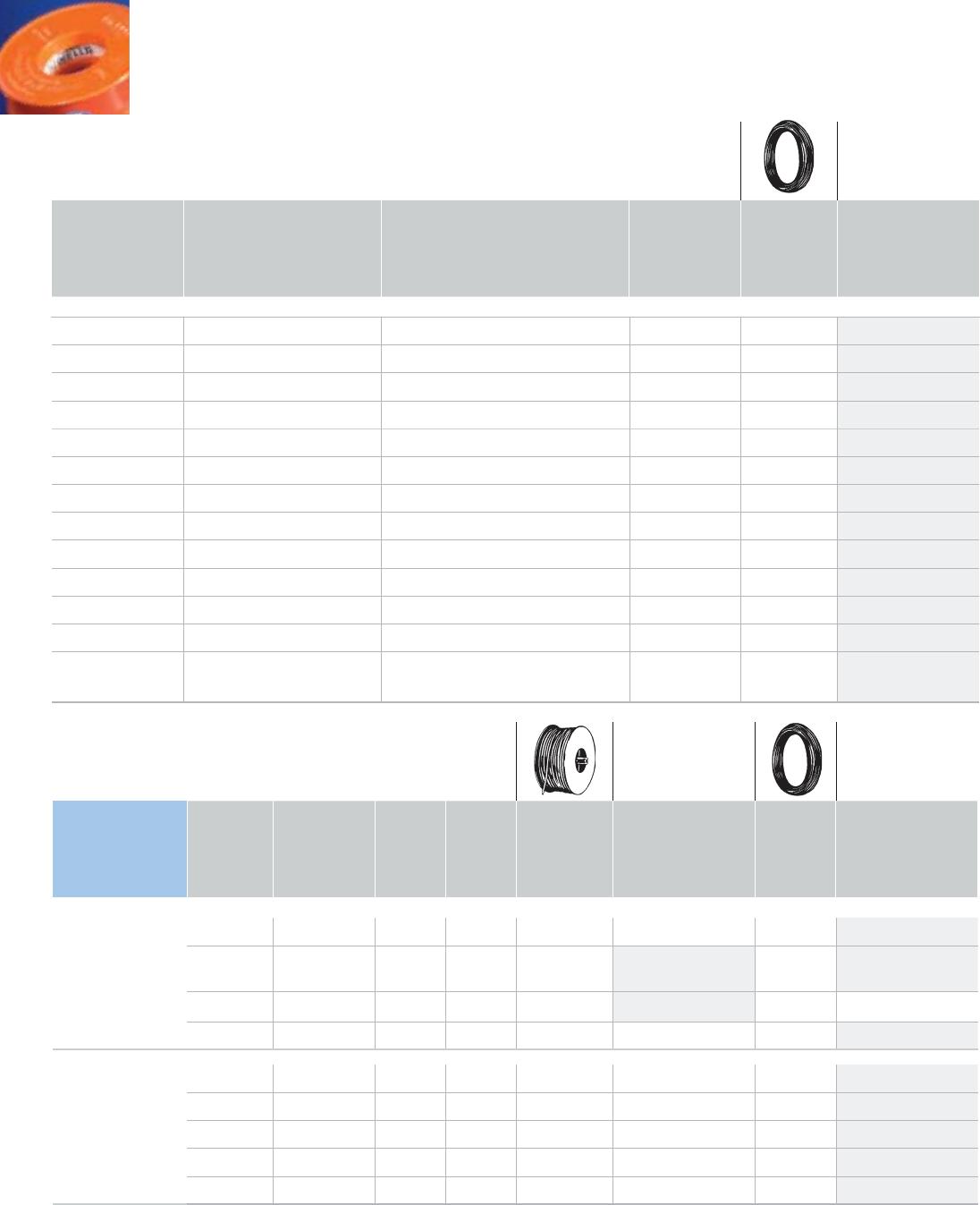
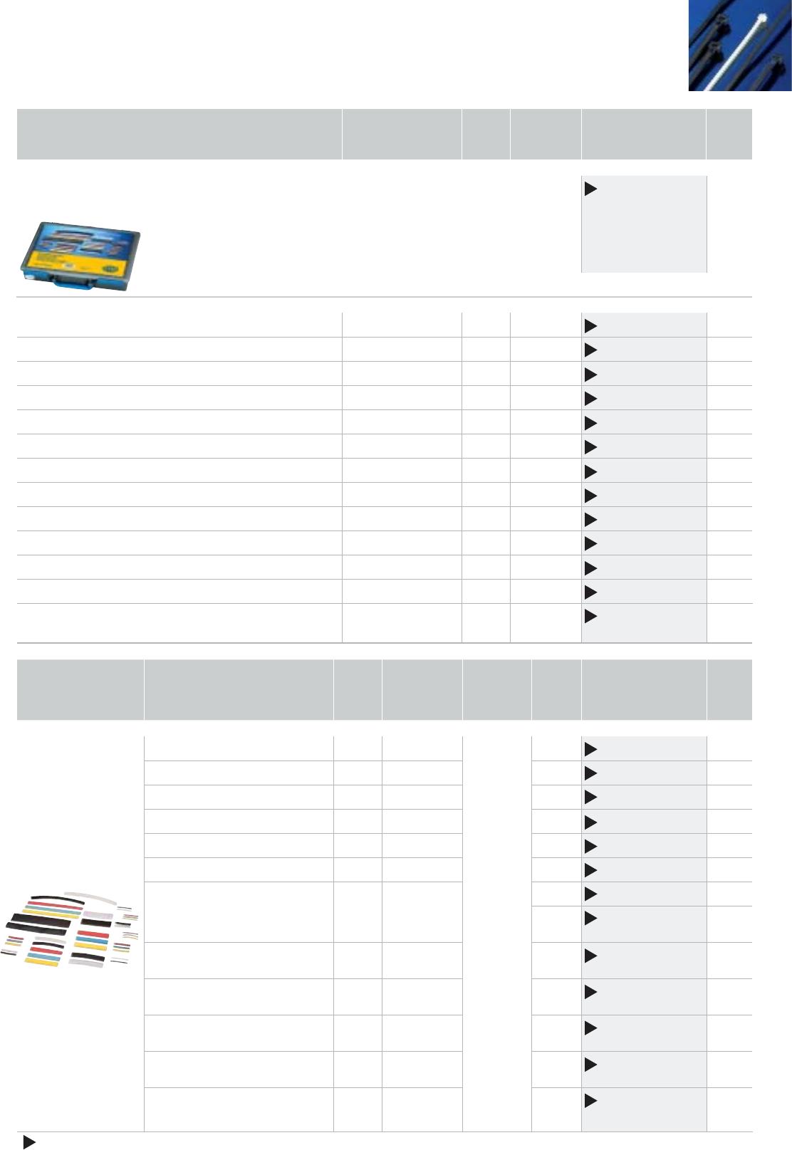
Heat shrink hose
assortment
Case containing an assortment of different heat shrink hoses with a shrink
rate of 2 : 1, usage temperature range of –55 to +125°C, flame-retardant
and self-extinguishing; UL224 shrinkage temperature min. 120°C
9MJ 178 458-801 1
20 each in red, yellow, blue 2.4 50 60 9MJ 178 458-002 1
30 each in black, transparent 2.4 50 60 9MJ 178 458-012 1
20 each in red, yellow, blue 3.2 50 60 9MJ 178 458-022 1
30 each in black, transparent 3.2 50 60 9MJ 178 458-032 1
20 each in red, yellow, blue 4.8 50 60 9MJ 178 458-042 1
30 each in black, transparent 4.8 50 60 9MJ 178 458-052 1
20 each in red, yellow, blue 6.4 50 60 9MJ 178 458-062 1
30 each in black, transparent 6.4 50 60 9MJ 178 458-072 1
4 each in red, yellow, blue, black, transparent 9.5 100 20 9MJ 178 458-082 1
4 each in red, yellow, blue, black, transparent 12.5 100 20 9MJ 178 458-092 1
10 each in black, transparent 19.1 100 20 9MJ 178 458-102 1
5 each in red, yellow, blue, black, transparent 9.5 200 25 9MJ 178 458-112 1
black 1 each in 5 x 19.1
and 25.4
200 10 9MJ 178 458-122 1
Colour Length Diameter
in mm
Temperature
range °C
Contents
in
pcs.
Part number PU
in pcs.
Heat shrink
hose sets
Shrink rate 2 : 1
20 each in red, yellow, blue 50 2.4 –55°C
to +125°C
60 9MJ 178 458-002 1
30 each in black, transparent 50 2.4 60 9MJ 178 458-012 1
20 each in red, yellow, blue 50 3.2 60 9MJ 178 458-022 1
30 each in black, transparent 50 3.2 60 9MJ 178 458-032 1
20 each in red, yellow, blue 50 4.8 60 9MJ 178 458-042 1
30 each in black, transparent 50 4.8 60 9MJ 178 458-052 1
20 each in red, yellow, blue 50 6.4 60 9MJ 178 458-062 1
30 each in black, transparent 50 6.4 60 9MJ 178 458-072 1
4 each in red, yellow, blue,
black, transparent
100 9.5 20 9MJ 178 458-082 1
4 each in red, yellow, blue,
black, transparent
100 12.5 20 9MJ 178 458-092 1
10 each in black, transparent 100 19.1 20 9MJ 178 458-102 1
5 each in red, yellow, blue,
black, transparent
200 9.5 25 9MJ 178 458-112 1
black 200
1 each in 5 x
19.1 and 25.4
10 9MJ 178 458-122 1
New in the range