|
32
INTRODUCTION 2
A small component with a big history . . . . . . . . . . . . . . . . . . . . . . . . . . . . . . . . . . . . . . . . . . . . . . . . . . . . 4
How HELLA checks and ensures quality . . . . . . . . . . . . . . . . . . . . . . . . . . . . . . . . . . . . . . . . . . . . . . . . . . 7
ELECTROMECHANICAL RELAYS 8
Explanation and uses . . . . . . . . . . . . . . . . . . . . . . . . . . . . . . . . . . . . . . . . . . . . . . . . . . . . . . . . . . . . . . . . . . 8
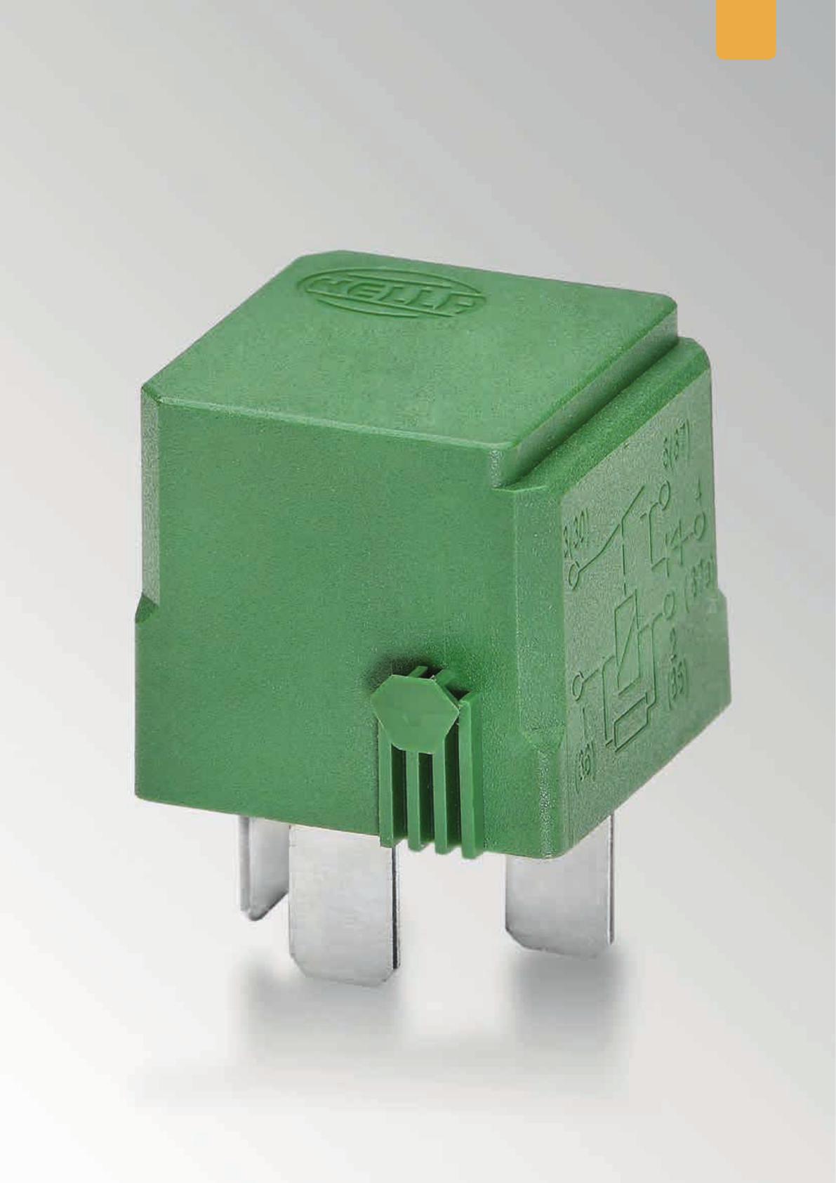
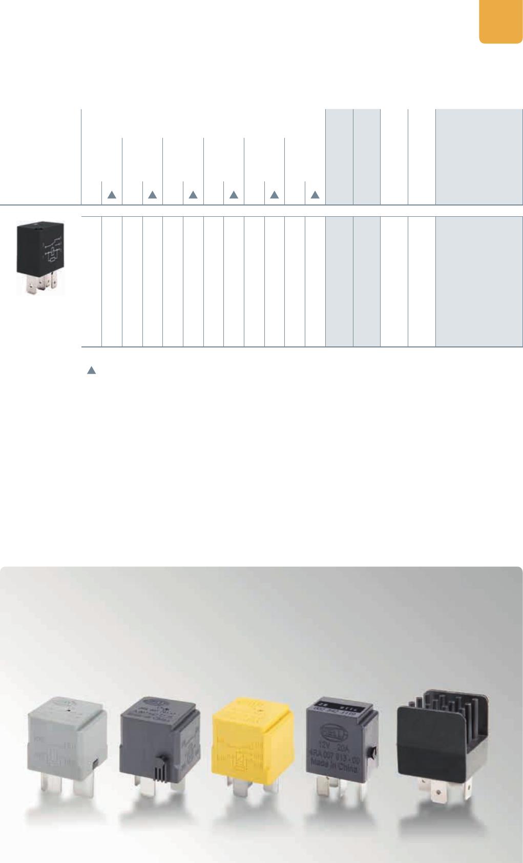
Relay types . . . . . . . . . . . . . . . . . . . . . . . . . . . . . . . . . . . . . . . . . . . . . . . . . . . . . . . . . . . . . . . . . . . . . . . . . .12
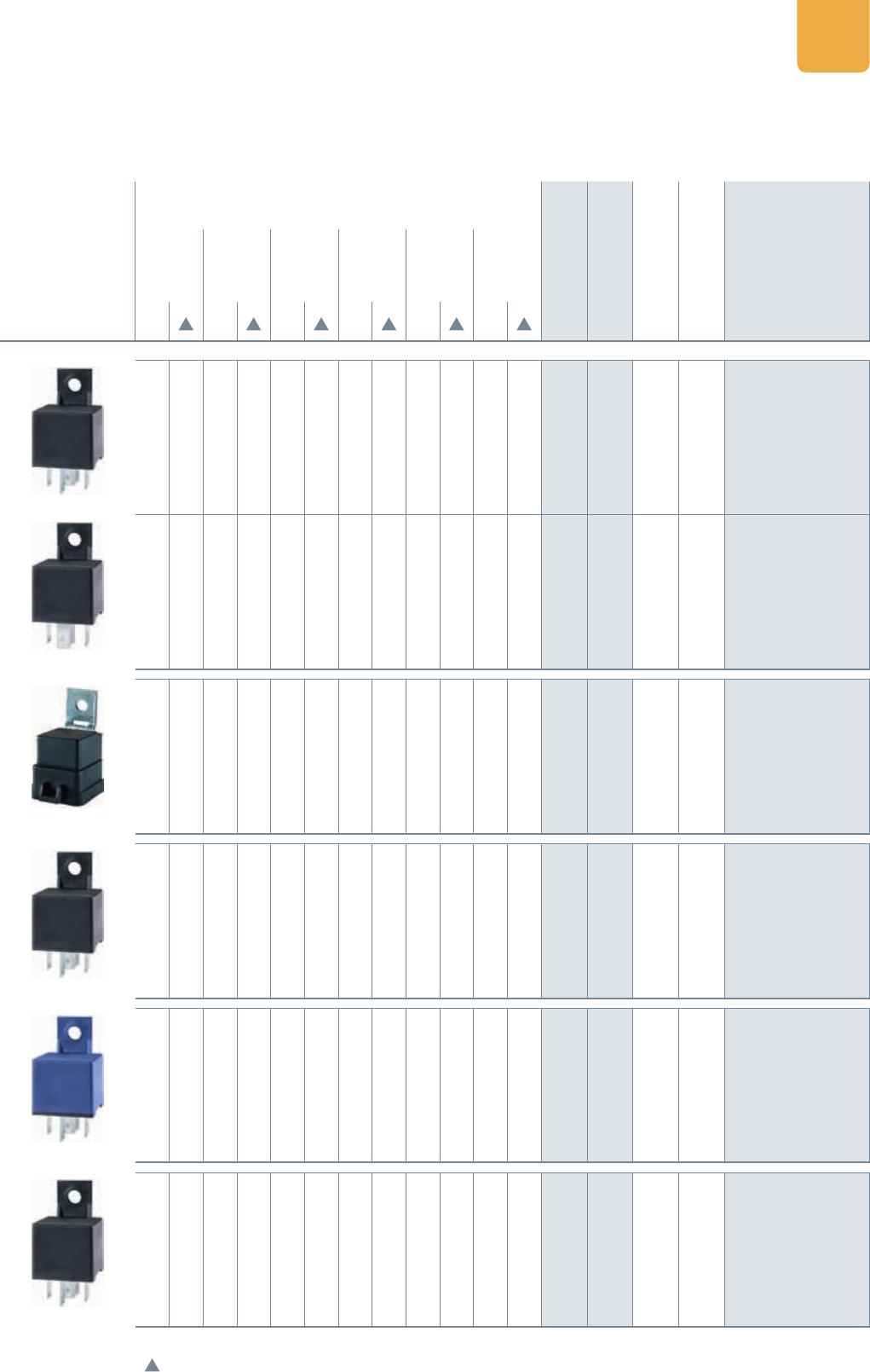
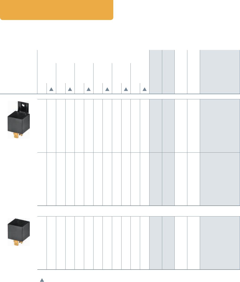
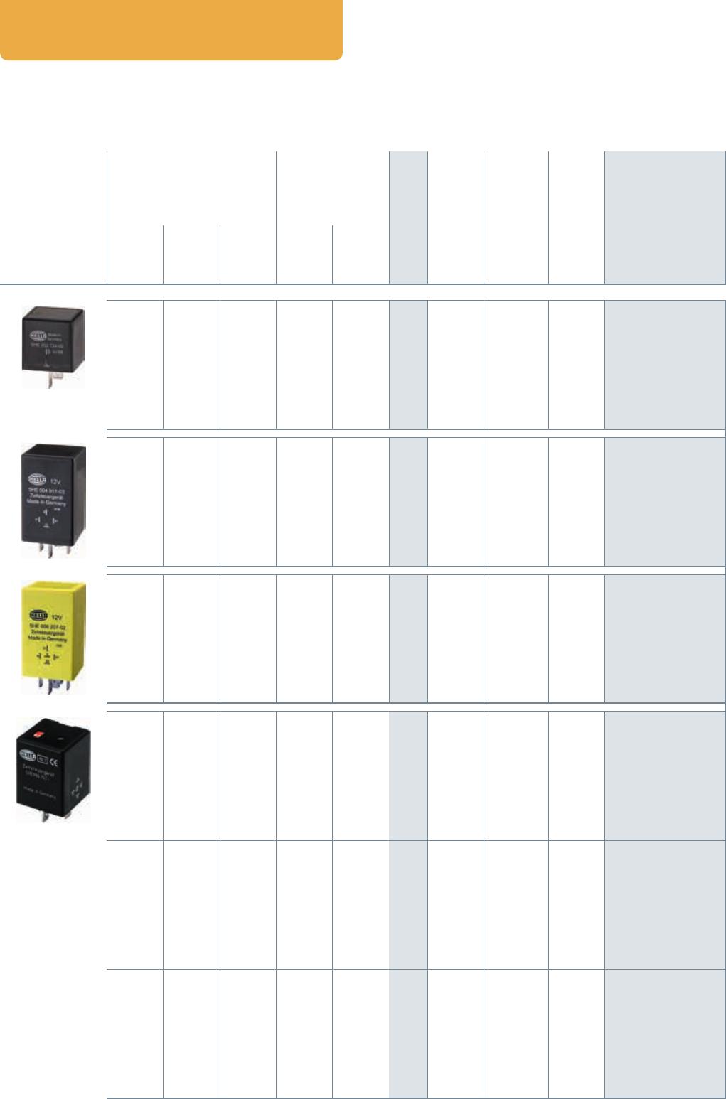
Mini relay 12 V – make contact with holder . . . . . . . . . . . . . . . . . . . . . . . . . . . . . . . . . . . . . . . . . . . . . .13
Mini relay 12 V, make contact without holder . . . . . . . . . . . . . . . . . . . . . . . . . . . . . . . . . . . . . . . . . . . . .14
Mini relay 12 V, change-over contact with holder . . . . . . . . . . . . . . . . . . . . . . . . . . . . . . . . . . . . . . . . . .15
Mini relay 12 V, make contact without holder . . . . . . . . . . . . . . . . . . . . . . . . . . . . . . . . . . . . . . . . . . . . .16
Mini relay 24 V – make contact with holder . . . . . . . . . . . . . . . . . . . . . . . . . . . . . . . . . . . . . . . . . . . . . .17
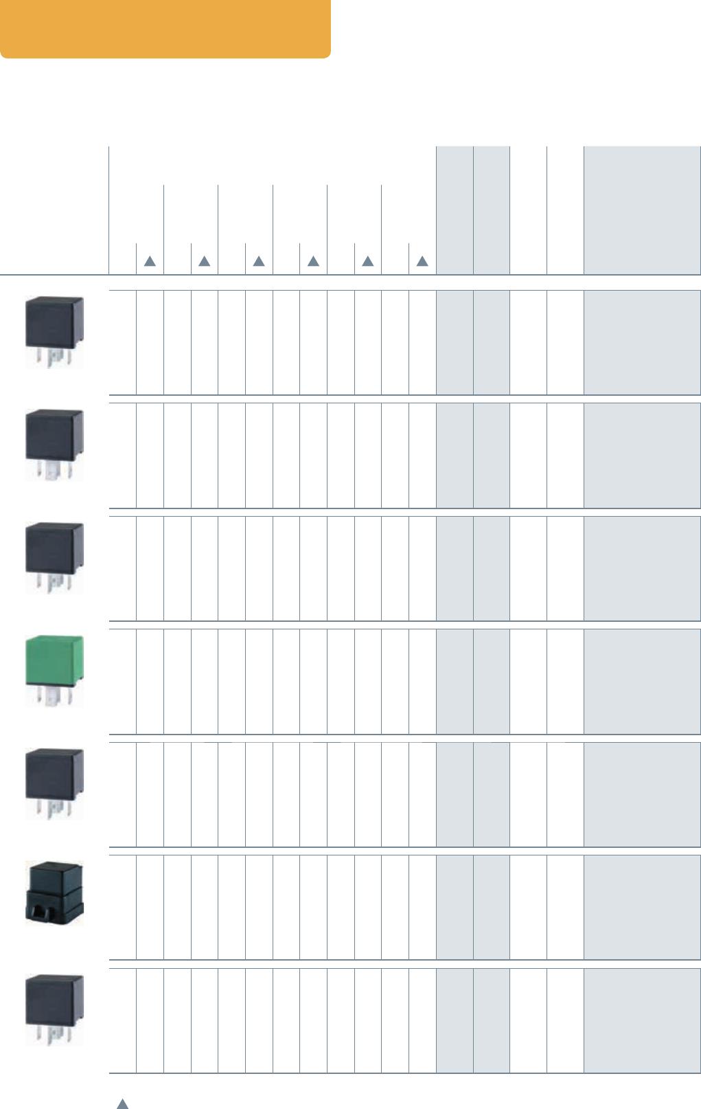
Mini relay 24 V, make contact without holder . . . . . . . . . . . . . . . . . . . . . . . . . . . . . . . . . . . . . . . . . . . . .18
Mini relay 24 V, change-over contact with holder . . . . . . . . . . . . . . . . . . . . . . . . . . . . . . . . . . . . . . . . . .19
Mini relay 24 V, make contact without holder . . . . . . . . . . . . . . . . . . . . . . . . . . . . . . . . . . . . . . . . . . . . .20
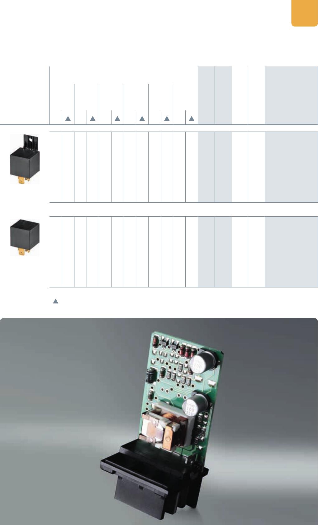
MICRO RELAY 22
Micro relay 12V, make contact without holder / change-over contact without holder . . . . . . . . . . 22
Micro relay 24V, change-over contact without holder . . . . . . . . . . . . . . . . . . . . . . . . . . . . . . . . . . . . . .23
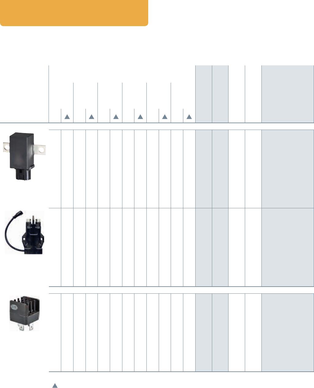
HIGHPOWER RELAY 24
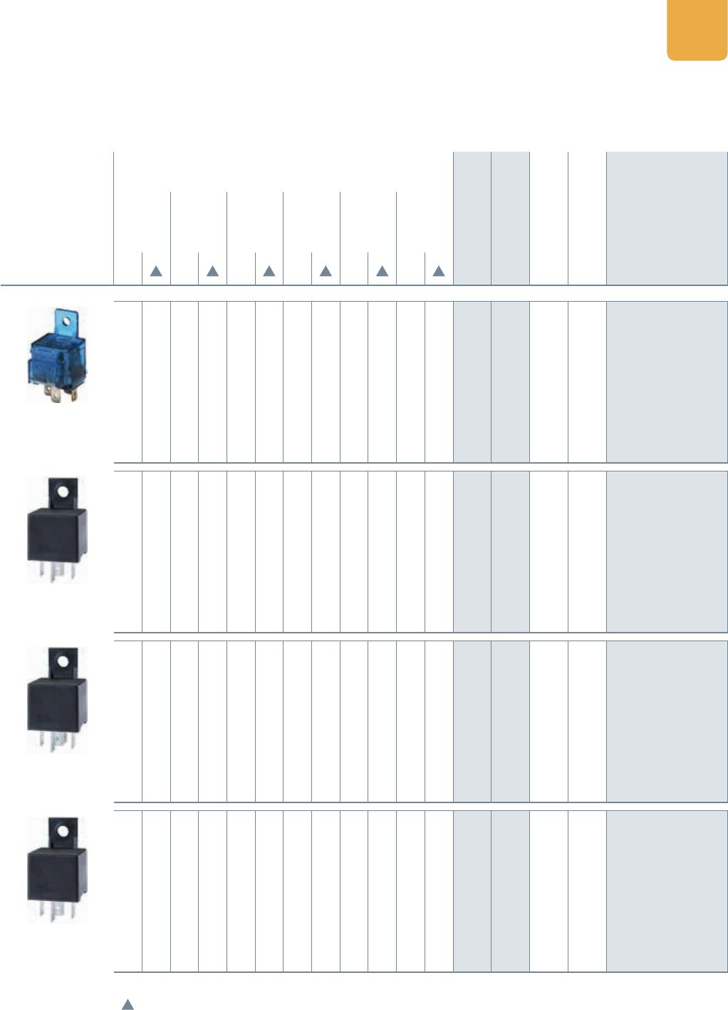
High-power relay 12V, make contact with holder/without holder . . . . . . . . . . . . . . . . . . . . . . . . . . .24
High-power relay 24V, make contact with holder/without holder . . . . . . . . . . . . . . . . . . . . . . . . . . .25
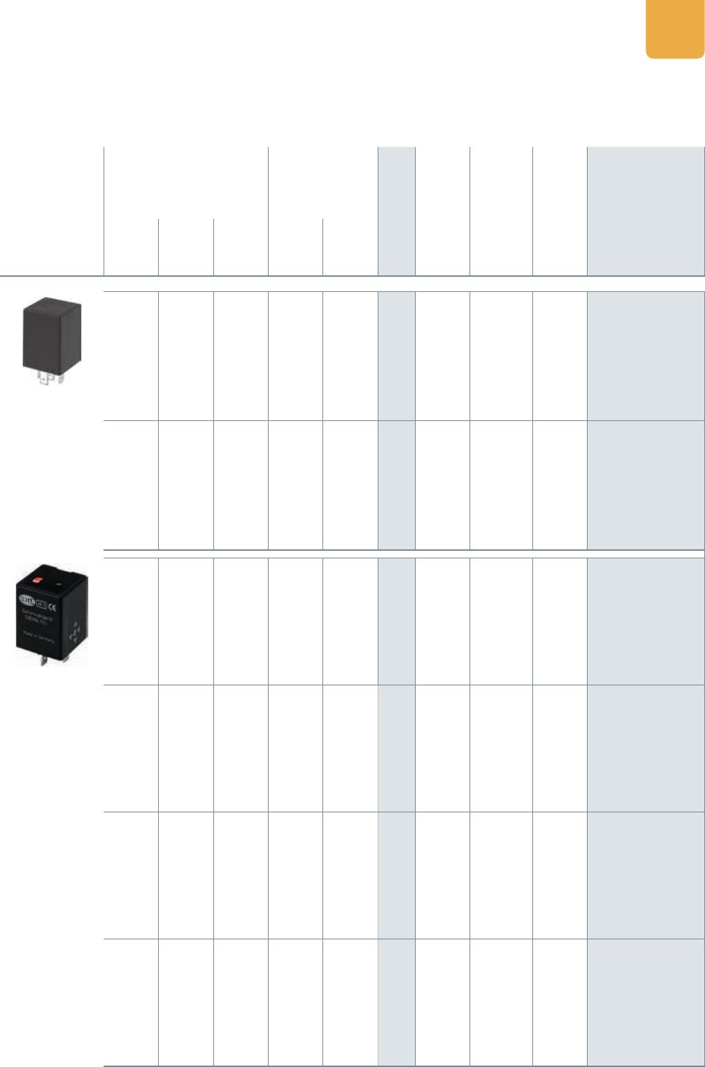
BATTERY DISCONNECT RELAY/SOLID STATE RELAY 26
Battery disconnect relay and solid state relay 12V, make contact . . . . . . . . . . . . . . . . . . . . . . . . . . .26
Summary of battery disconnect and solid state relays . . . . . . . . . . . . . . . . . . . . . . . . . . . . . . . . . . . . .27
TECHNICAL DATA 28
Technical data of the relays – Overview . . . . . . . . . . . . . . . . . . . . . . . . . . . . . . . . . . . . . . . . . . . . . . . . . .28
Climatic and mechanical tests . . . . . . . . . . . . . . . . . . . . . . . . . . . . . . . . . . . . . . . . . . . . . . . . . . . . . . . . . .30
FLASHER UNITS 32
Explanation and uses . . . . . . . . . . . . . . . . . . . . . . . . . . . . . . . . . . . . . . . . . . . . . . . . . . . . . . . . . . . . . . . . . 32
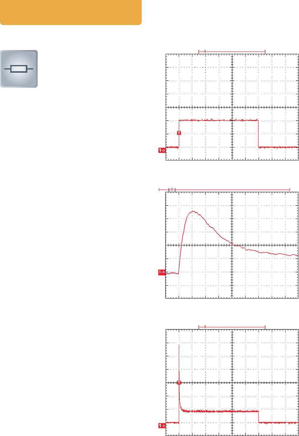
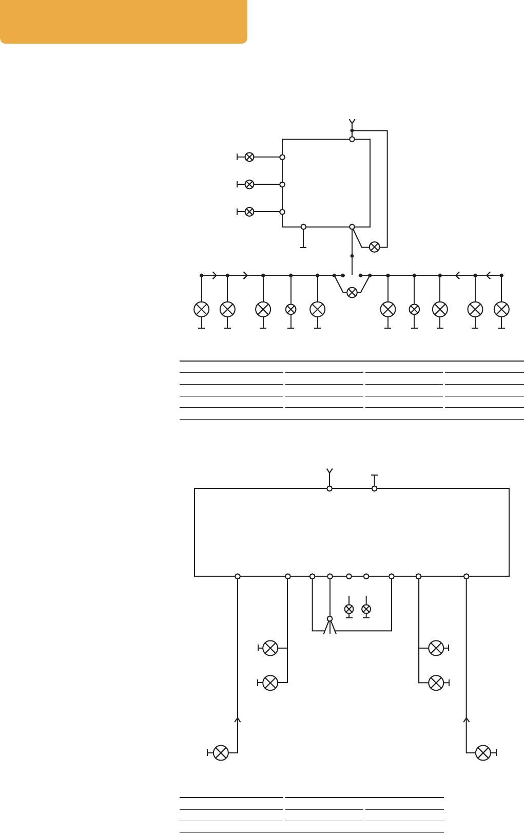
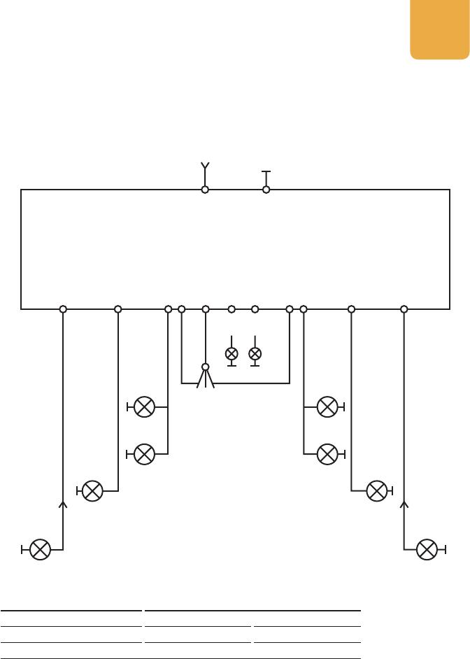
Test circuits . . . . . . . . . . . . . . . . . . . . . . . . . . . . . . . . . . . . . . . . . . . . . . . . . . . . . . . . . . . . . . . . . . . . . . . . . . 36
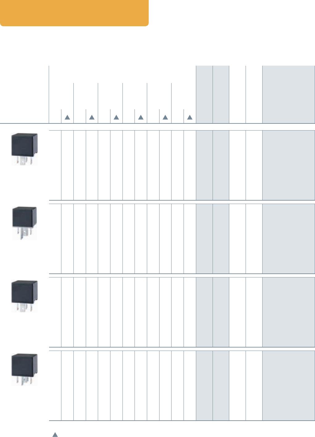
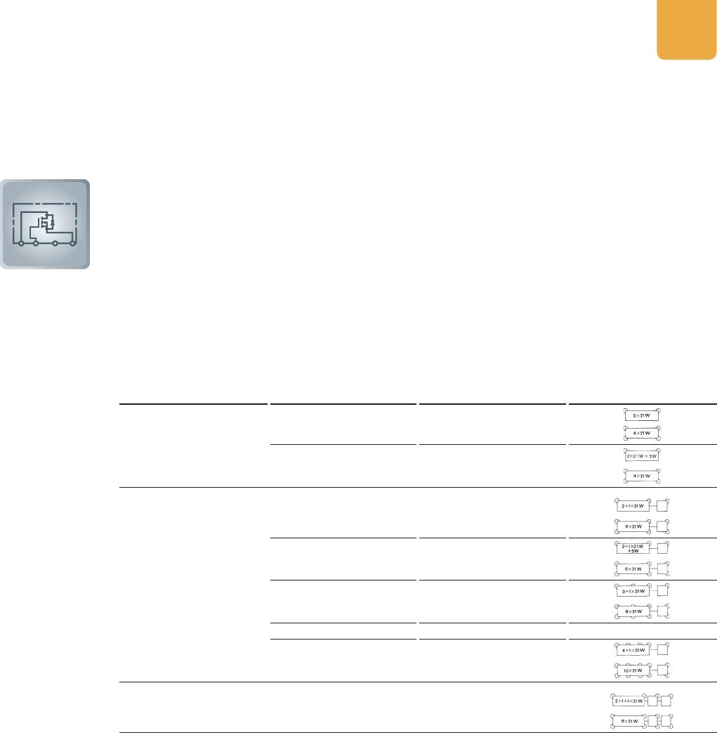
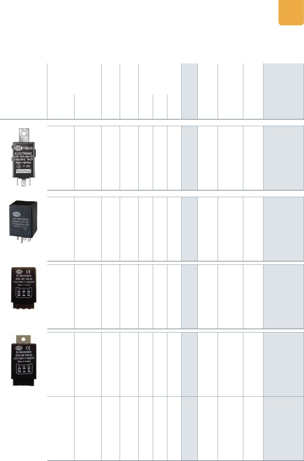
Flasher unit 6V, 4-pole and 12V, 3-pole . . . . . . . . . . . . . . . . . . . . . . . . . . . . . . . . . . . . . . . . . . . . . . . . . . 38
Flasher unit 12V, 3-pole . . . . . . . . . . . . . . . . . . . . . . . . . . . . . . . . . . . . . . . . . . . . . . . . . . . . . . . . . . . . . . .39
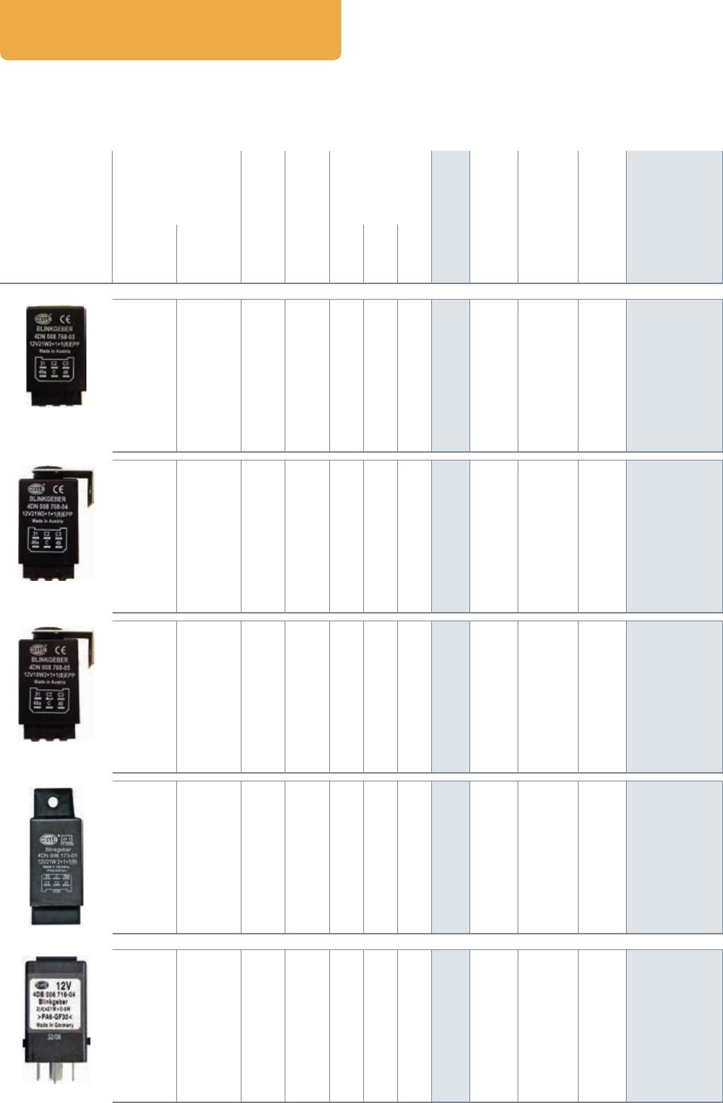
Flasher unit 12V, 4-pole . . . . . . . . . . . . . . . . . . . . . . . . . . . . . . . . . . . . . . . . . . . . . . . . . . . . . . . . . . . . . . .40
Flasher unit 12V, 5-pole/6-pole . . . . . . . . . . . . . . . . . . . . . . . . . . . . . . . . . . . . . . . . . . . . . . . . . . . . . . . .41
Flasher unit 12V, 6-pole/7-pole . . . . . . . . . . . . . . . . . . . . . . . . . . . . . . . . . . . . . . . . . . . . . . . . . . . . . . . .42
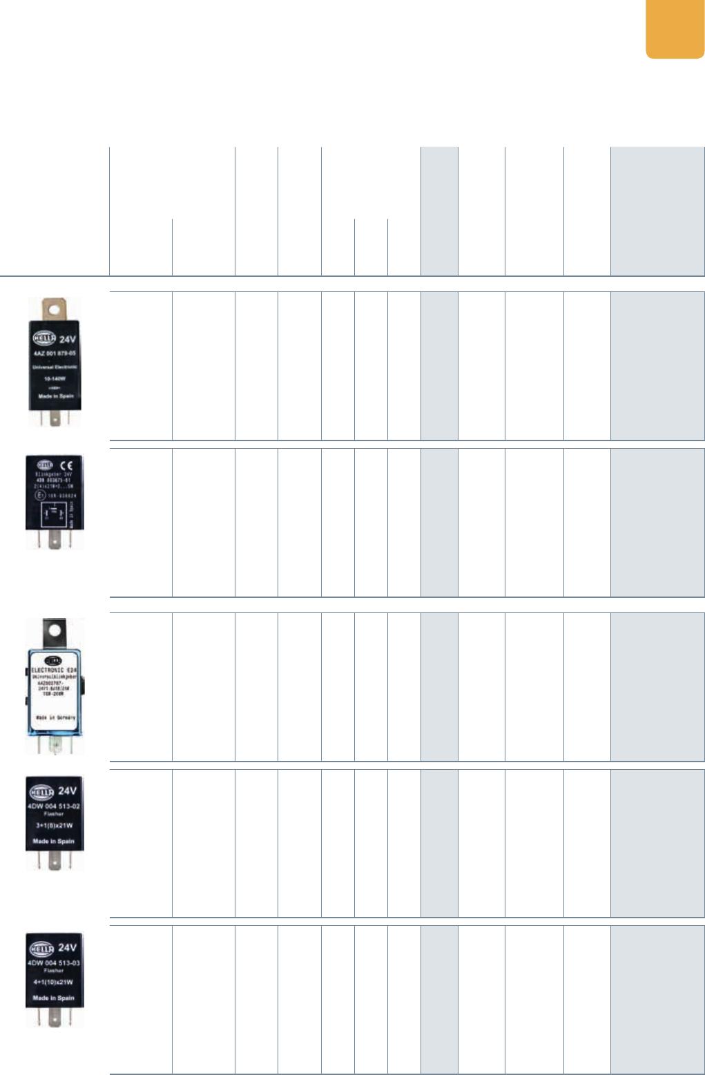
Flasher unit 24V, 3-pole/4-pole . . . . . . . . . . . . . . . . . . . . . . . . . . . . . . . . . . . . . . . . . . . . . . . . . . . . . . . .43
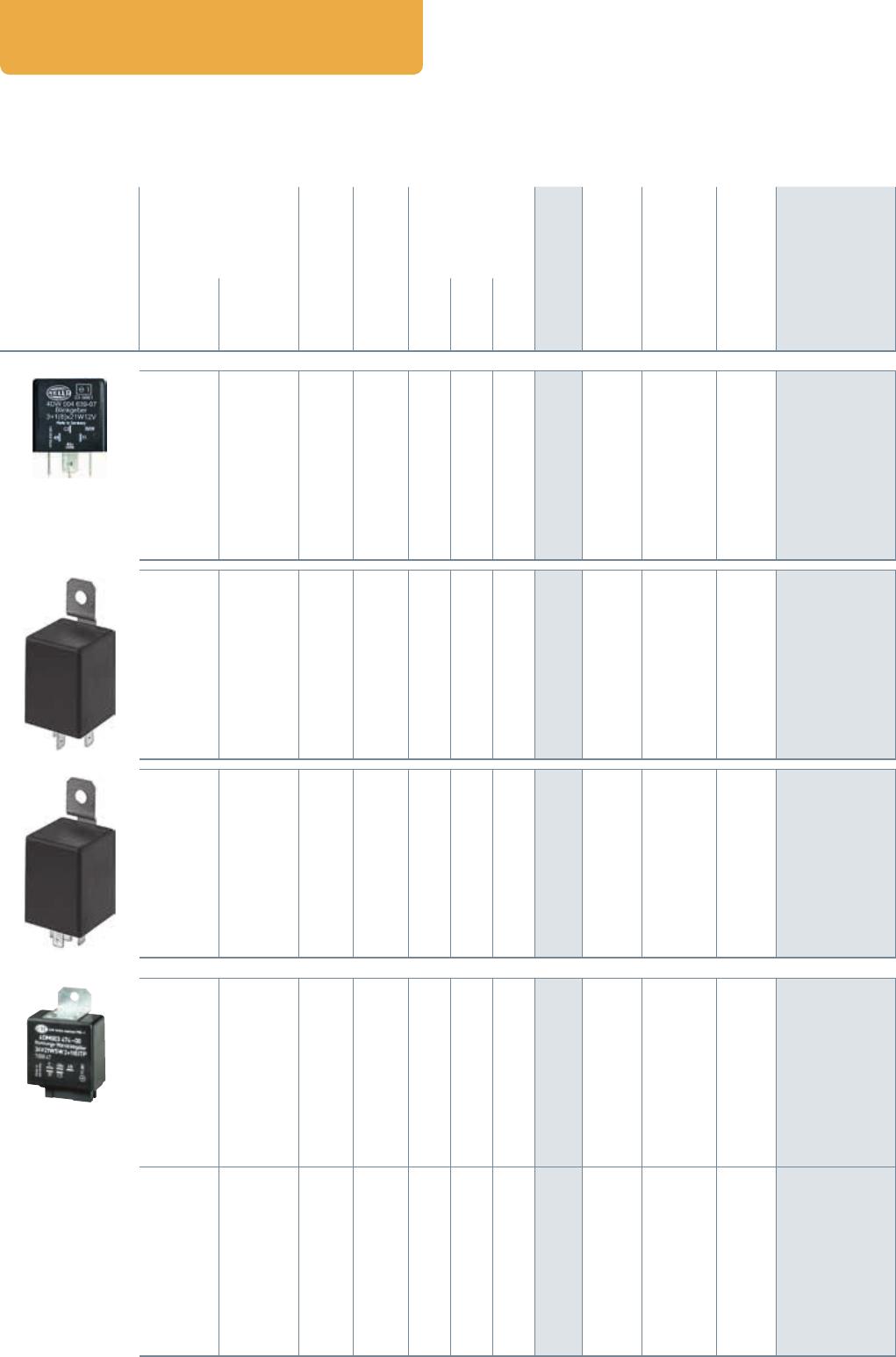
Flasher unit 24V, 4-pole/5-pole . . . . . . . . . . . . . . . . . . . . . . . . . . . . . . . . . . . . . . . . . . . . . . . . . . . . . . . .44
Flasher unit 24V, 6-pole/7-pole . . . . . . . . . . . . . . . . . . . . . . . . . . . . . . . . . . . . . . . . . . . . . . . . . . . . . . . .45
Flasher unit 24 V, 11-pole and 12/24 V, 6-pole . . . . . . . . . . . . . . . . . . . . . . . . . . . . . . . . . . . . . . . . . . .46
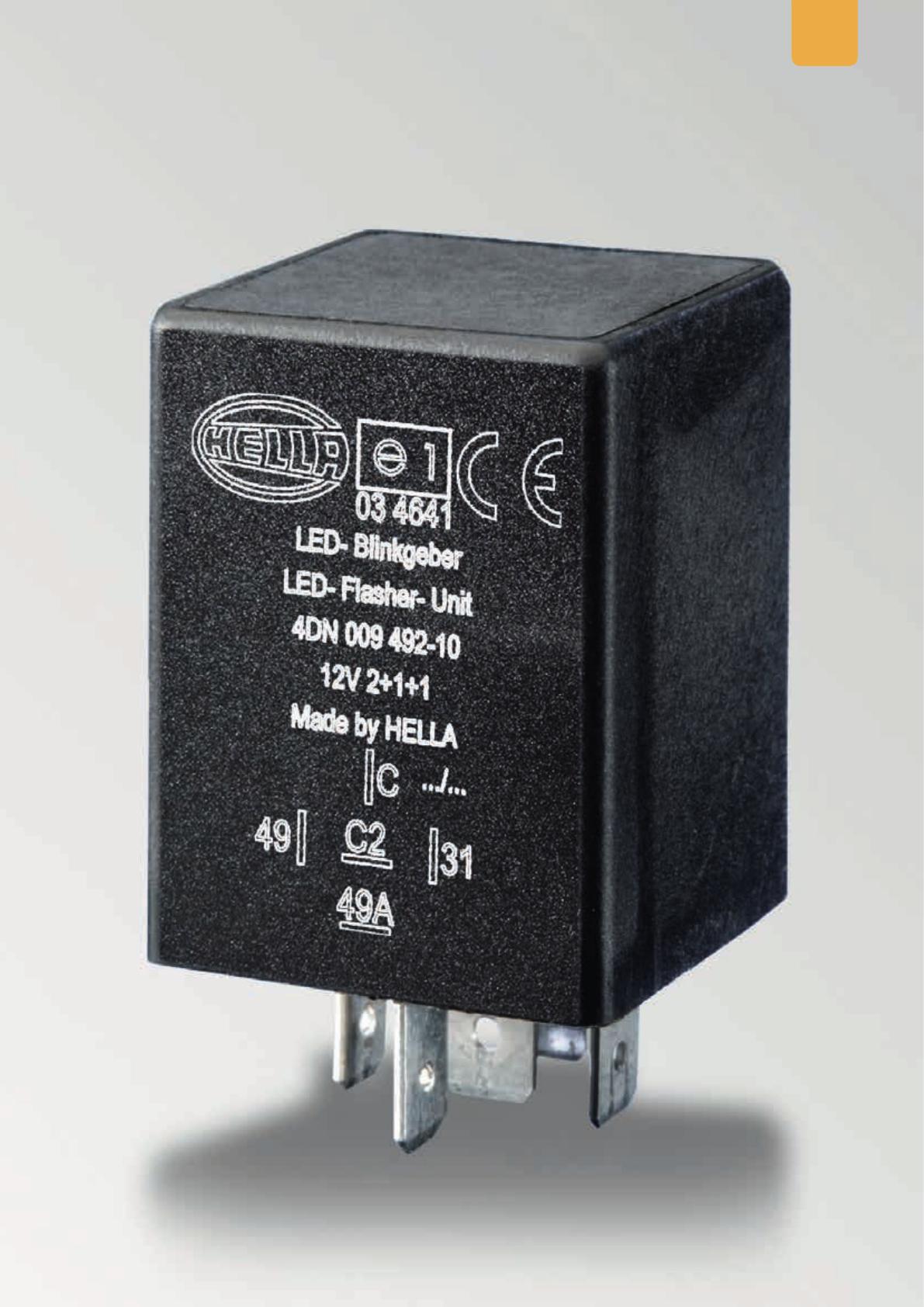
LED fl asher unit 12/24V, 3-pole; 12V, 4-pole/5-pole and 24V, 4-pole . . . . . . . . . . . . . . . . . . . . . . . .47
Overview of fl asher unit technical data . . . . . . . . . . . . . . . . . . . . . . . . . . . . . . . . . . . . . . . . . . . . . . . . . . 48
Legal regulations for fl asher units . . . . . . . . . . . . . . . . . . . . . . . . . . . . . . . . . . . . . . . . . . . . . . . . . . . . . .48
LED indicators and failure control from HELLA . . . . . . . . . . . . . . . . . . . . . . . . . . . . . . . . . . . . . . . . . . .49
The right solution for your vehicle electronics . . . . . . . . . . . . . . . . . . . . . . . . . . . . . . . . . . . . . . . . . . . .50
WASH/WIPE INTERVAL CONTROL UNITS 52
Explanation and uses . . . . . . . . . . . . . . . . . . . . . . . . . . . . . . . . . . . . . . . . . . . . . . . . . . . . . . . . . . . . . . . . . 52
Wash/wipe interval control units 12V . . . . . . . . . . . . . . . . . . . . . . . . . . . . . . . . . . . . . . . . . . . . . . . . . . .54
Wash/wipe interval control units 24V . . . . . . . . . . . . . . . . . . . . . . . . . . . . . . . . . . . . . . . . . . . . . . . . . . .55
Headlight cleaning system 12V/24V . . . . . . . . . . . . . . . . . . . . . . . . . . . . . . . . . . . . . . . . . . . . . . . . . . . . .56
CLOCK RELAYS 58
Explanation and uses . . . . . . . . . . . . . . . . . . . . . . . . . . . . . . . . . . . . . . . . . . . . . . . . . . . . . . . . . . . . . . . . . 58
Clock relays 12V . . . . . . . . . . . . . . . . . . . . . . . . . . . . . . . . . . . . . . . . . . . . . . . . . . . . . . . . . . . . . . . . . . . . . .60
Clock relays 24V . . . . . . . . . . . . . . . . . . . . . . . . . . . . . . . . . . . . . . . . . . . . . . . . . . . . . . . . . . . . . . . . . . . . . .61
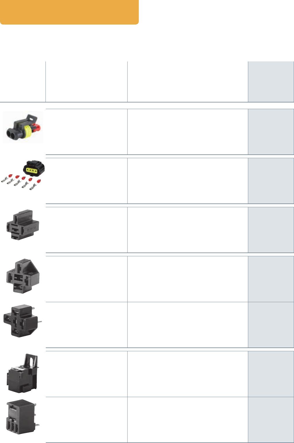
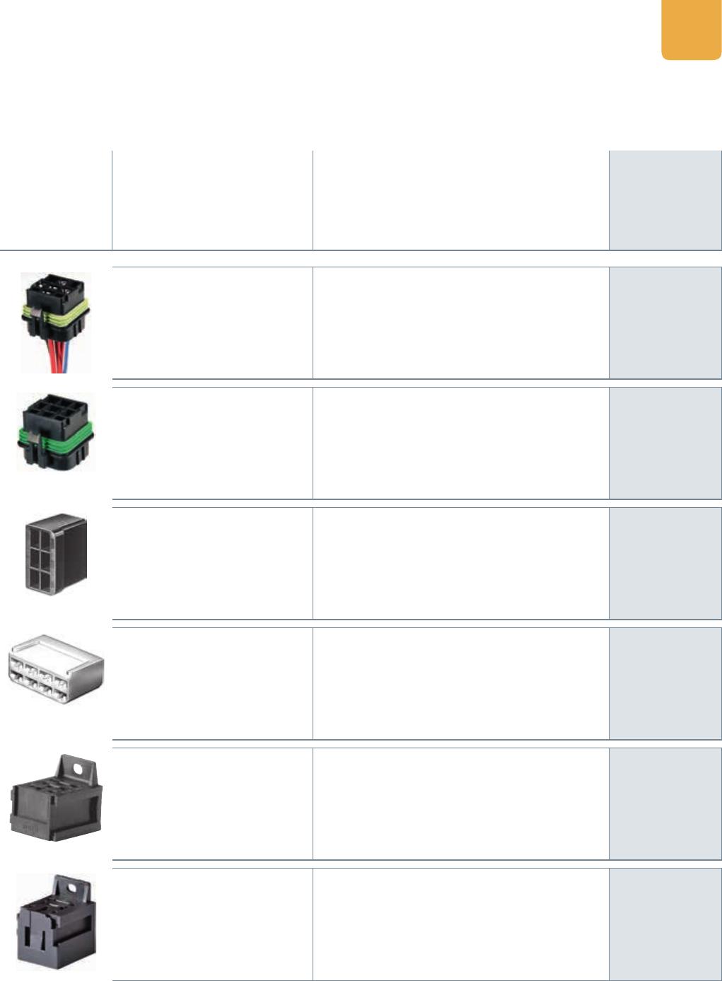
ACCESSORIES 62
Overview . . . . . . . . . . . . . . . . . . . . . . . . . . . . . . . . . . . . . . . . . . . . . . . . . . . . . . . . . . . . . . . . . . . . . . . . . . . .62
SWITCHING AND PLUG MATRICES 64
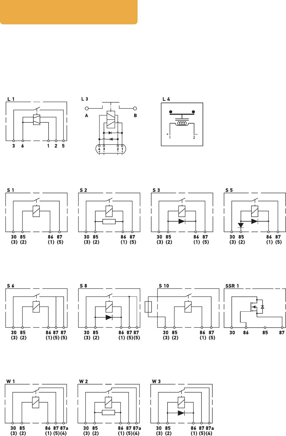
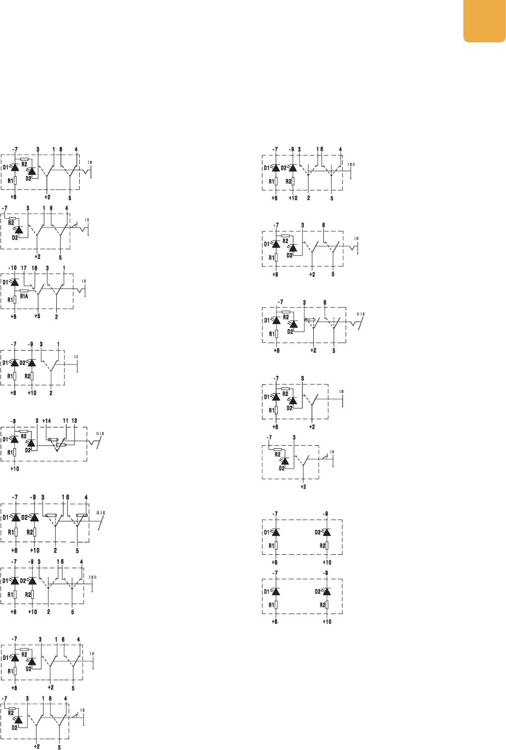
Circuit diagrams – electromechanical relays . . . . . . . . . . . . . . . . . . . . . . . . . . . . . . . . . . . . . . . . . . . . .64
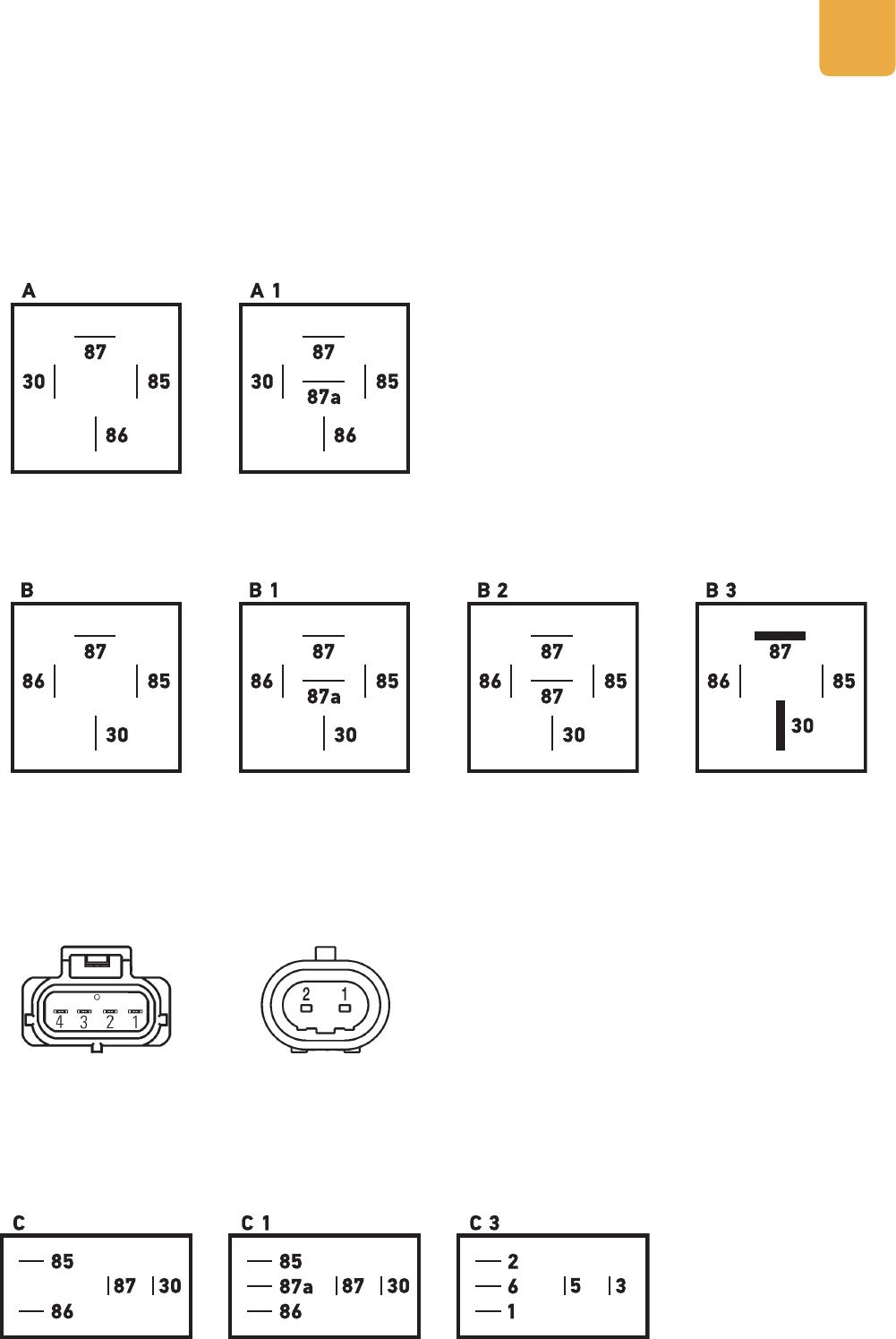
Pin diagrams – electromechanical relays . . . . . . . . . . . . . . . . . . . . . . . . . . . . . . . . . . . . . . . . . . . . . . . .65
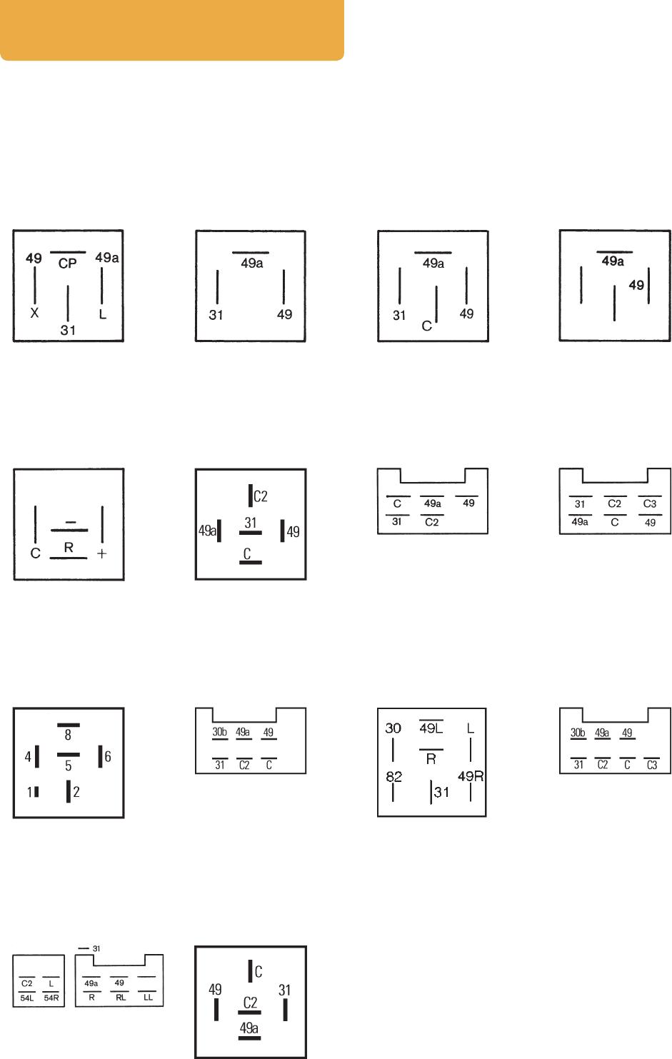
Pin diagrams – fl asher units . . . . . . . . . . . . . . . . . . . . . . . . . . . . . . . . . . . . . . . . . . . . . . . . . . . . . . . . . . .66
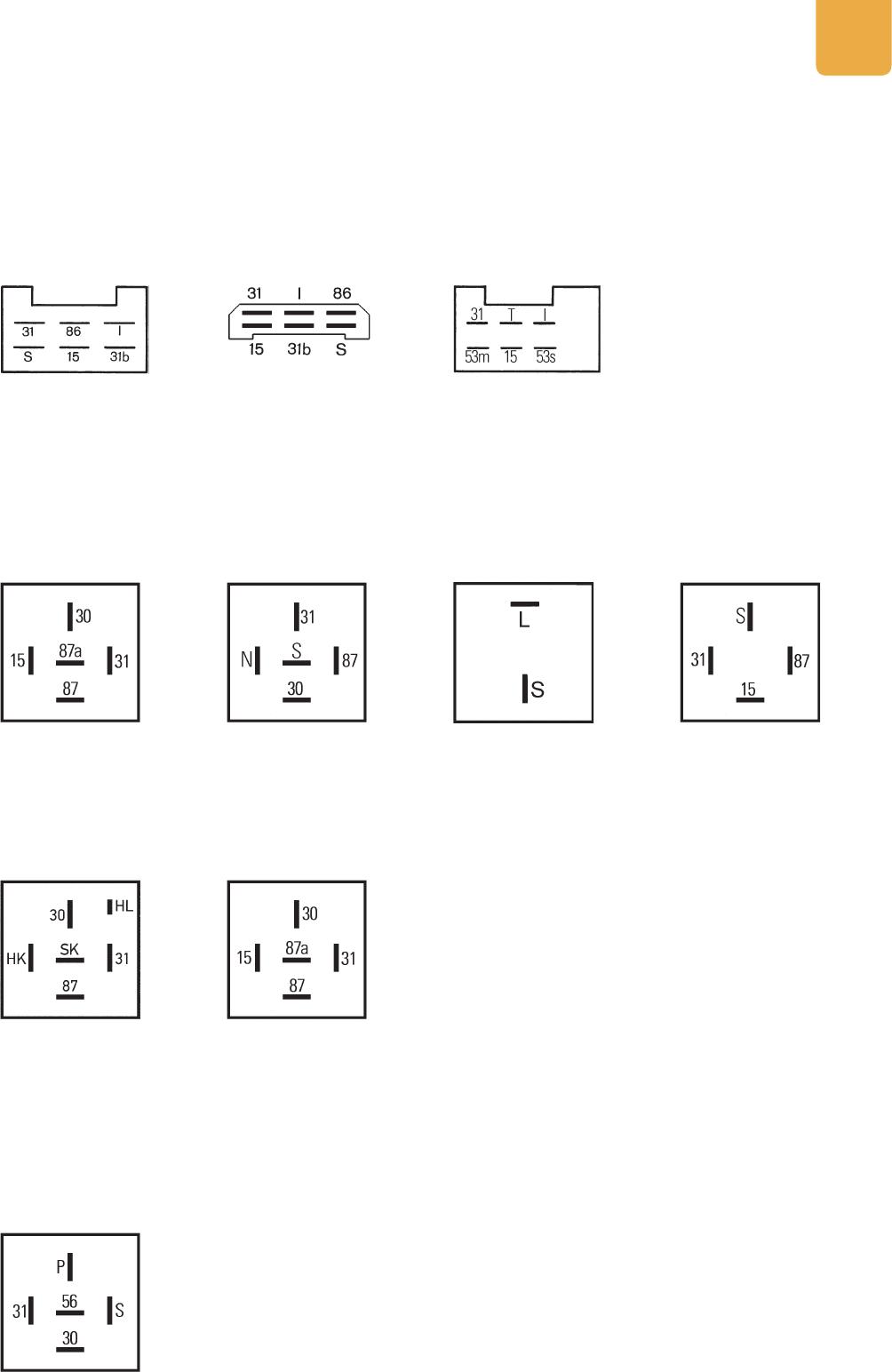
Pin diagrams – wash/wipe interval control units . . . . . . . . . . . . . . . . . . . . . . . . . . . . . . . . . . . . . . . . .67
Pin diagrams – clock relays . . . . . . . . . . . . . . . . . . . . . . . . . . . . . . . . . . . . . . . . . . . . . . . . . . . . . . . . . . . . 67
Pin diagrams – control units for headlight cleaning systems . . . . . . . . . . . . . . . . . . . . . . . . . . . . . . . 67
HELLA ROCKER SWITCHES 68
The new HELLA switch confi gurator . . . . . . . . . . . . . . . . . . . . . . . . . . . . . . . . . . . . . . . . . . . . . . . . . . . . 68
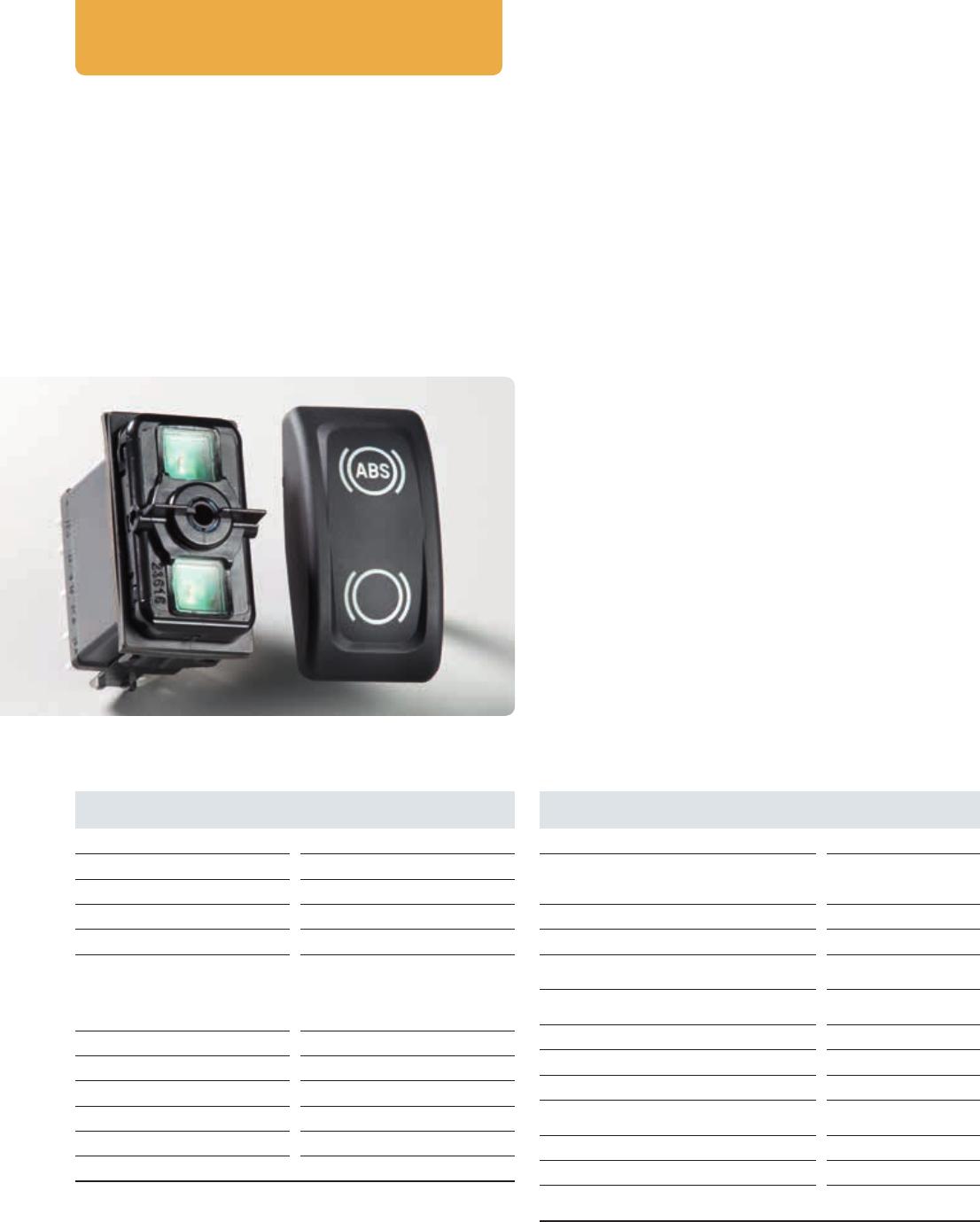
Rocker switch, 3100 series. . . . . . . . . . . . . . . . . . . . . . . . . . . . . . . . . . . . . . . . . . . . . . . . . . . . . . . . . . . . .70
Switch functions . . . . . . . . . . . . . . . . . . . . . . . . . . . . . . . . . . . . . . . . . . . . . . . . . . . . . . . . . . . . . . . . . . . . . . 71